This is an unusual project in that it was
not inspired by any actual need. Rather, the Rope Winder
(and its prototype seen at bottom) were envisioned because of
a flawed Cub Scout manual. The manual in question directed the
adults to simply twist wet strings together to produce the rope.
This is not how rope is produced, since stable rope requires
that the major strands and the strings of which they are made
have opposite twists to keep it from unwinding. The inspiration
here was purely for a desire to set the record straight for Cub
Scouts learning the fundamentals of common materials.
The mechanical rope winder was originally
designed roughly about the time of the American Civil War. The
final product will produce stable rope when being used by young
Cub Scouts. Materials used are plywood (with a gloss gray epoxy
finish), nylon gears and bushings, bicycle sprockets & chain,
and other custom-built components.
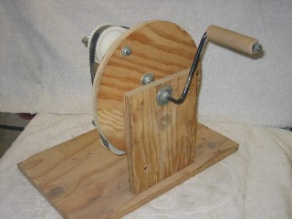
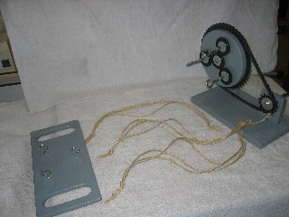
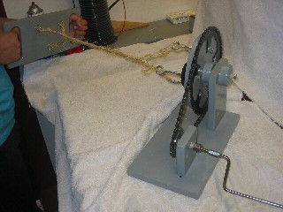
The system (below left) consists of the
rope winder itself, and a hooked board (on the left) to hold
both ends of the strings, since the rope-to-be must be kept under
tenson until finished. The photo (below left) shows the crank
handle on the shaft used for providing the initial twist to the
individual fibers. The mounting block for the the smaller sprocket
is movable (see the slot in the lower right photo) to keep the
chain taut, or to release it for maintenance and repair.
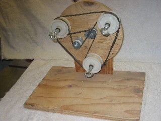
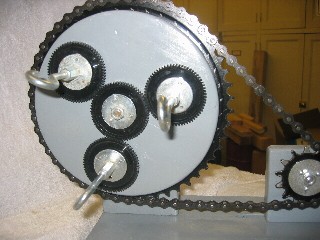
The crank handle is on the cable-twisting
shaft (above right) for use after the strand fibers have been
given their twist. The close-up photo (below left) shows both
the strand-twisting gear mechanism, and the rope-twising chain-and-sprocket
arrangement. The strings are ready and tied at each end to be
attached to the hooks on the board at left, and to the twisting
hooks on the rope-winder itself (below right).
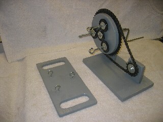
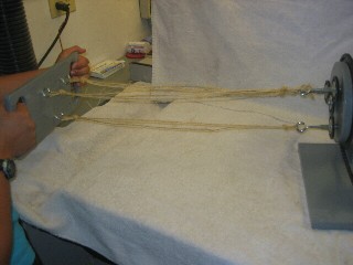
With the hooked board, and strings in place
(below left), the crank handle is turned (clockwise) on the rope
winder (below right) to put the initial twist to the rope strands.
Nylon gears were used (see above left) to reverse the direction
of twist. This was to keep both twisting operations using a clockwise
direction so as not to confuse the cub scouts.
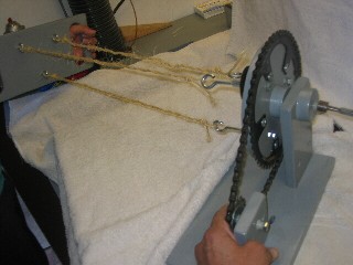
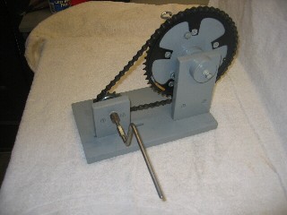
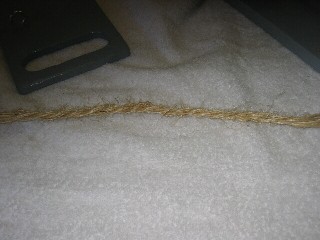
The hand crank is moved to the left-hand
shaft (below left) and turned clockwise to impart the final twist
to the new rope. The combination of clockwise and counter-clockwise
twists serves to keep the final product (below right) stable
and free from the tendency to unwind. For best results, the winder
should be clamped to a table, and the hook board on the left
kept with the strings under constant tension so that the rope
does not bunch up until both sets of twists have been applied.
The original prototype (below) went through
many design revisions to understand the operation of the original
(historical) mechanism. Although the prototype does not produce
good rope, the multiple phases it went through were sufficient
to understand the proper mechanism. It is also convenient to
leave concerns about finished appearance out of the initial development
stage.